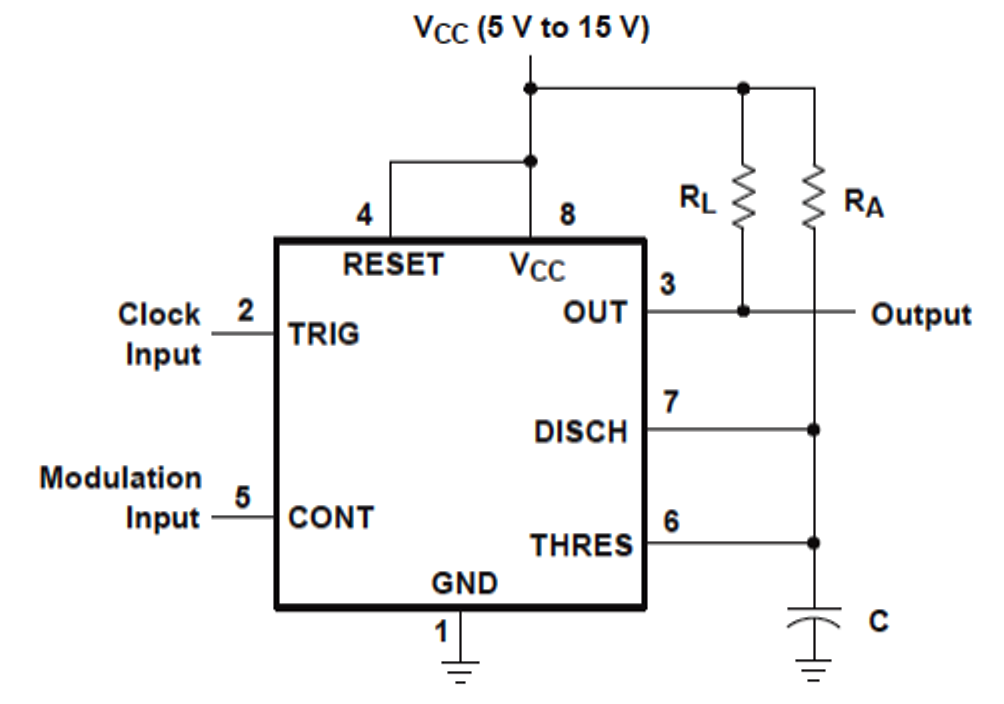
Potentiometer controlled behaving properly schematics forgive newbie How to use ic 555 for generating pwm outputs Circuit design
Cpu cooler | TechPowerUp Forums
4-wire fans Pwm fan diagram wiring fans motherboard cpu cooler control ec speed case pc does power plug rgb controller wire work Fan connector motherboard wire fans circuit logic example
Cpu cooler
Pinout wiring pwm corsair header motherboard fans ventilator brushless gpu gnd cooling tweakers 4pin obsolete pines buzzer continous beeping 5vWhat is pwm and how does it work? Pwm 555 circuit motor dc control speed power circuits fan astable mosfet igbt diagram electronicos timer 90vdc functional difference various555 pwm circuit ic use diagram using simple generating generate mode circuits pinout monostable configuration following learn let outputs easy.
Pwm wat is het, hoe gebruik ik het met mijn fan en waterpompPwm ventilador ekwb motherboard wires headers connectors ventiladores therefore .

Cpu cooler | TechPowerUp Forums

PWM wat is het, hoe gebruik ik het met mijn fan en waterpomp - Cooling

circuit design - 4-wire fan controlled by potentiometer and 555 IC not

How to Use IC 555 for Generating PWM Outputs | Circuit Diagram Centre

4-Wire fans

What is PWM and how does it work? - ekwb.com